
 I’ve been interested in this project for a while, but finally have had the time and parts to follow through. My initial implementation is on an ATTiny461, but I’ve ordered some ATTiny4s to play around with as well.
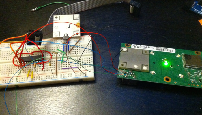
The basic premise is that the RF board on a Xbox360 uses 3.3v USB to communicate and with some inf file changes, we can use it on a PC! Only issue is that you can’t sync a controller. There are workarounds (Play-n-charge kits), but I’d rather this be self-contained to take on the road. So, the only option is to use a microcontroller to trigger the RF board to sync. I used an ATTiny461 because it’s what I had lying around the house, but people have used Raspberry Pis, Arduinos, and PICs. As long as you have some IO pins, you’ll be fine.
The post above mentioned to use some diodes to bring down the voltage, but I would rather have something that can handle different loads. I ended up reusing one of the voltage regulators from the 360 itself. The one I picked is an NCP1117. It’s an adjustable regulator that’s a drop in replacement for the LM317. I destroyed another RF board when trying to desolder the connector, so I used the metal shield on it for a heatsink. A couple of resistors later, and I now have 3.3v at up to 1A!
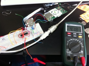 The code is adapted from a few different variants on the page, but is functionally the same. It will perform a LED init, then send the animation command and wait for the power button to be pressed to perform a sync. One thing I got sidetracked with was reducing the power consumption of the 461. Idle draw was 4.2mA when I started, and was 0mA when I was done. The biggest change was putting the microcontroller asleep instead of leaving it to idle in a busy loop. The power button is hooked to the external INT0 pin, so I can set it to a very low powered sleep mode. The RF board draws the most power anyways, so the 461’s draw becomes negligible over long periods of time. IIRC, the RF board draws around 95mA when doing nothing, and 130mA during the startup animation.
All that’s left is to print an enclosure (Thanks Chris!), and assemble it permanently with an ATtiny4! I’ll add schematics and STLs once they’re ready.